
Over the years, regular readers of this column will have seen articles on air handling, winterizing and weatherproofing transmitter sites and similar topics. For this edition, I thought it would be useful to show what can happen when these subjects are not properly addressed. To that end, I’m including a story written by David Kilpatrick, of TX Australia, outlining the steps he took to restore a fairly new transmitter that had suffered damage as a result of exposure to too much environment!
The reason for this is twofold:
First, David has written a comprehensive troubleshooting guide that could be of use for other repair situations.
Second, it includes a very complete description of steps to take to repair UG69, Tectrol power supplies. As these supplies are outsourced, we are unable to provide repair facilities for them. The original manufacturer had been offering a great price on rebuilding damaged supplies, but has recently raised the rate to where factory repair is not economically viable. Hopefully David’s article can assist some folks with repairs on these units.
Two things of note:
First, the supplies we use have been upgraded to a platinum series for several years – these have higher volume fans, better dust protection and efficiency. In some cases, there is a good argument to be made for wholesale replacement – however, that does leave a lot of older supplies that, in good working order, could be used for emergency spares… the repair tips below may help with that.
Second, I need to give credit where it is due – this article is the result of a post that David originally made in one of the technical forums on the Virtual Engineer website – this is a great resource for engineering folks and is frequented by some technical types who are a whole lot smarter than I am. It is definitely a site worth joining and adding to your bookmarks.
Now to David’s story, as written in the Virtual Engineer (edited only to improve flow for a single article, vs. a series of posts):
I thought the board might be interested to follow the progress of a project I’m currently working on, which is the repair and restoration of a Nautel NV20 transmitter. This TX was installed about 7 years ago; I imagine some of you thinking “why does a 7-year-old Nautel need to be restored?”.
Well sadly for this transmitter it was installed with little regard to filtering the outside air used to cool it. In this particular location the summer air becomes quite humid, and the site is located quite close to a major metropolitan road (carrying many cars and trucks).
Over time the moisture from the air condensed inside the unit (mixed with the diesel engine pollution) and found it’s way into most of the power supply units and PA modules. The final nail in it’s coffin was a roof-leak during a storm dumping extra water into the unit. Insurance paid for a replacement TX, the room was converted to closed-loop air conditioned cooling, and the NV20 was abandoned by the previous owner.
Initial investigation shows the power supply modules appeared to have suffered the most amount of damage. The PA modules have some dirt and grime on the output PCB where the fans are located, but otherwise they appear to be okay. The AUI computer and control PCB are undamaged, and I am yet to inspect the exciters.
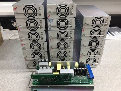
If there was going to be any chance of restoring this transmitter, the power supplies seemed like a reasonable place to start. In this model there are 20 main power supplies – 16 for each of the PA modules (plus 2 more for each of the IPA modules contained therein), and 2 power supplies for PA and reject load fans.
These are made in Canada by Tectrol, and in total there were 18 power supplies identified as faulty or dead.
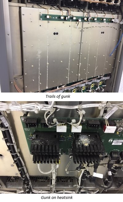
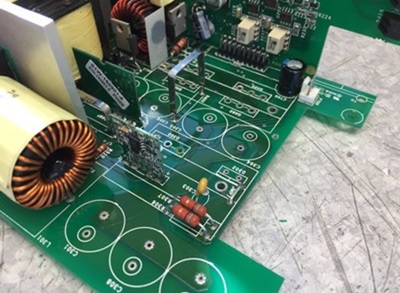
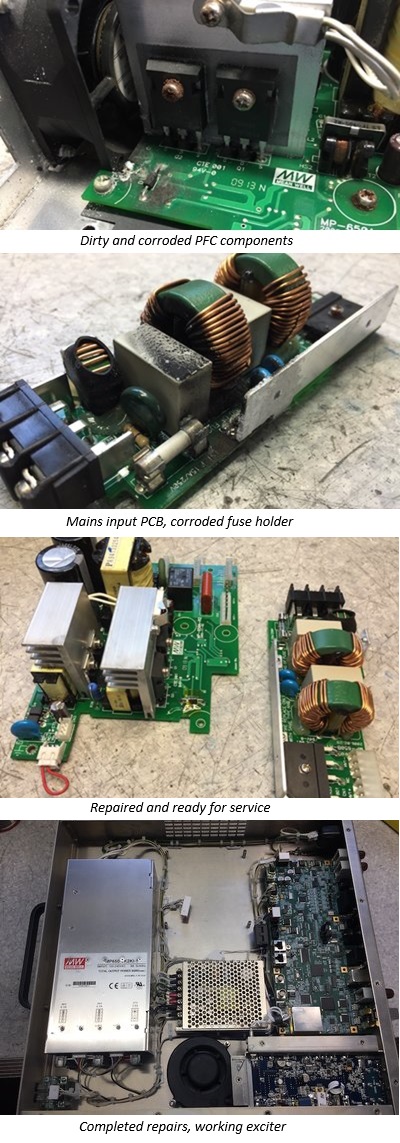
The most common reason for failure was moisture and dirt build-up around the heatsink and MOSFET associated with the power factor correction section.
At the base of the heatsink is a wire jumper, connected to the +400V main DC bus (later revisions of this power supply have omitted this jumper).
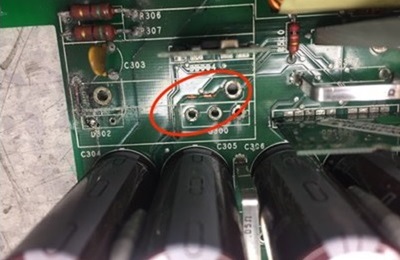
When a short circuit between +400V and the heatsink occurs, the first casualty is the PCB trace that grounds the heatsink. The collateral damage this causes typically destroys the MOSFET, diode, and PFC control IC, a PIC micro-controller, and one or both main fuses.
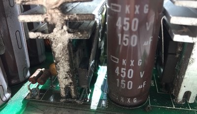
Sometimes the main rectifier is damaged, but most survive. Corrosion typically damages the snubber resistors and capacitor for the PFC MOSFET, and the main filter caps closest to the fan.
Repair consists of removing all the components at the ‘front-end’ of the supply, cleaning the PCB and repairing any damaged tracks.
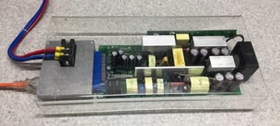
New parts are installed and then the power supply is load-tested at 1024W (32V @ 32A) for 30 minutes. Here is one running underneath my plastic “blast shield”. Fortunately it has not yet had to live up to it’s name!
The power supply is attached to a in-house test fixture to provide a safe means of connecting power and load. It also provides feedback of the various alarm signals from the PSU (which the transmitter monitors), and provides the means to vary the output voltage using a 0 to 5 volt control signal (again, something the transmitter does in normal operation).
All 20 power supplies have been repaired and tested, along with 2 spare units. This is a good result and greatly increases the chances of this transmitter living again!
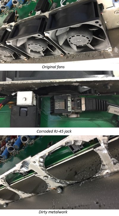
The 8 PA modules were the next items to work on, which have all suffered from drawing in dirty moist air. The damage was mostly confined to the PCB directly behind the fans, which splits the output of the IPA to drive the final PA stages and distributes DC power to the cooling fans.
Each PA was stripped of it’s cooling fans and supporting metalwork, along with the damaged PCB. Most of the parts on the PCB were removed (fan connectors, RJ-45 jacks, enable switch, and various other parts) and then the board was given a thorough wash to remove dirt.
All new parts have been installed, including brand new cooling fans, as most original parts had been damaged by dirt and water causing corrosion.
The metalwork was cleaned by soda blasting to remove dirt and corrosion, then given a light scrub with a Scotch Brite pad, and finally a wash in warm water. The result is not factory-fresh, but they are certainly quite serviceable.
The 3 photos shown here are ‘before’ pictures.
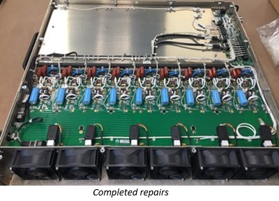
Here is the completed PA just prior to re-attaching the lid.
As I delve further into this transmitter there is a pattern beginning to form. Any component/PCB/whatever that sits less than 2 inches behind a fan will require attention.
The exciter contains 2 power supply modules. A high power module for the PA output stage, and a low power module for the exciter logic board. Since the high power PSU has a fan, it was no surprise to find out it had failed.
The high power PSU is manufactured by MeanWell, model MP650. It provides 48v @ 12.6A and 27v @ 5.8A.
Internally the PSU is broken down into various modules which plug together (modules are for mains input, power factor correction and auxiliary supply, and DC output module for each rail).
With the fan blowing moist dirty air directly onto the power factor correction (PFC) module, this is where the fault occurred. I am reasonably certain that the PFC switching MOSFET shorted out, sending a spike of 400V towards the PFC controller IC.
This spike then found it’s way onto the auxiliary 12V supply, which then went on to damage the DC output modules.
Replacement parts were sourced and installed – PFC controller IC, PFC switching MOSFET, main DC bus voltage detection IC, PWM controller IC and switching MOSFET for each DC output module, and various SMD resistors and diodes which were fried as collateral damage.
All up a rather satisfying result when both PSU modules fired up and were tested at full load (650W total). So now the transmitter has 2 working exciters again.
Some more progress was made with a few smaller jobs ticked off the list:
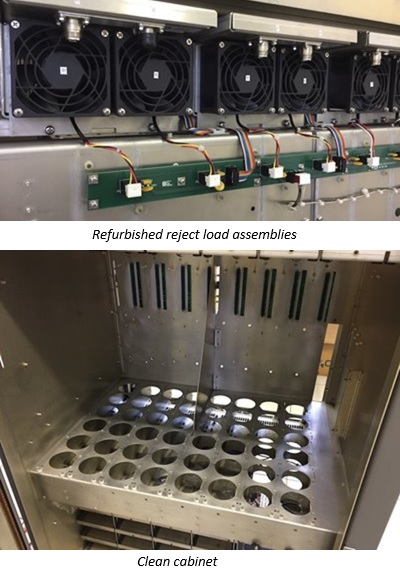
The transmitter contains a number of internal reject loads to absorb mismatched power, which contain a built-in directional coupler to measure the amount of reject power. The reject loads had to be stripped down, cleaned and repaired (replacing corroded IDC ribbon cable connectors).
Fresh heatsink compound was placed under each load resistor (72 resistors in total), and new fans and ribbon cables were also fitted.
The PA module backplane PCBs were removed and cleaned, as well as PCBs for low voltage distribution.
The 4 low-voltage power supplies (all made by MeanWell) were checked and found to be all operational after a quick clean and load test. New fans were fitted to the pair of 12 volt supplies for the AUI computer and display.
Cleaning of the transmitter cabinet was also accomplished to remove surface dirt and corrosion from the metalwork directly beneath the PA modules.
All the PC boards were washed using Electrolube Safe Wash Super (SWAS), followed by a rinse with distilled water, and dried with warm air. Connectors were additionally cleaned with IPA. Also, any stubborn flux was removed with Chemtronics FluxOff prior to the SWAS treatment.
More progress to report, with the last of a few small jobs taken care of:
Install new blower fans into front door including new connectors
Re-install low voltage power supply modules
Re-connect reject loads
Re-install and connect modulators
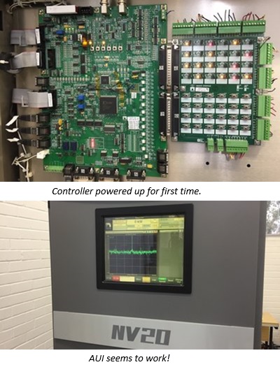
With the low voltage power supplies installed and all connections double-checked, it was time to apply power so that the TX controller, AUI computer and monitor could be checked out.
Power on; the controller appeared to come to life and after a few moments the AUI screen showed the computer booting up. Power was applied to the exciters and the AUI had no problems connecting to them.
It was quite encouraging and satisfying to see all these individual parts come together to form a functional transmitter again.
Now for the real test!
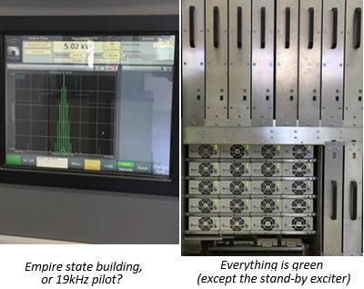
Power was removed, and a colleague of mine (Tom) connected the transmitter to a 25kW test load with some 3-1/8″ rigid while I enlisted some help to re-install the 8 PA modules and 20 power supply modules.
A silent prayer was said as power was turned on again. Nothing went bang, or smoked. A preset was duly selected on the AUI to bring the transmitter up to minimum power at switch on (about 600 watts). Pressing RF ON, various fans whirred to life, power supply modules all began to supply DC, and the AUI reported 0.6kW forward power.
There was no difficulty raising the power to 5kW, then to 10kW. This is the maximum TPO that could be achieved with the transmitter connected to it’s temporary power circuit, but I have little doubt it would be capable of the full 20kW.
So there you have it. The repair and restoration of a Nautel NV 20 that was damaged by years of inhaling dirty, humid air and eventually storm water.
Excellent job, Dave, thanks so much for sharing this with the folks at the Virtual Engineer and for allowing me to reprint here!
To get back to my original point, while Dave has done an amazing job here, realize that this took place over roughly a three-month span and could have been avoided totally with proper air handling and weatherproofing of the transmitter site. It truly is one of those situations where paying a little could have saved a lot.
Jeff
Jeff Welton, has worked with Nautel for 25+ years. He is currently the Nautel Sales Manager for U.S. Central Region but previously he spent 16.5 years as a Nautel Customer Service Technician.
Submissions for this Tips ‘n Tricks column are encouraged and if published you’ll receive a Nautel T-shirt. Submissions should be typed and emailed, with high resolution photos, to info@nautel.com using the subject line Tips ‘n Tricks.
