With the rush to get ready for NAB and the mayhem of the show floor, rather than coming up with something original, I’m cheerfully stealing an article written for our Navigator Newsletter. Since this newsletter goes out to a whole different customer set, I figured most of you won’t have seen it already!
The article deals with building an RF current probe – in AM sites, this can be extremely useful in many ways. First, for checking for the presence of RF on a wire and for adjusting tuning to null or peak the current flow (think tuning an RF drive amplifier for example). It’s also a good way to check RF currents in ground radials, to see if you’ve got a broken radial, although it does require some digging to uncover the radials.
Side note – there’s a way to check ground radial integrity with a field strength meter that doesn’t involve digging; FREE swag goes out to the first person who emails me that procedure and we’ll put it in the next issue of Waves!.
One word of caution on the article below – where it specifies a turn of wire around a toroid, remember that a turn consists of every time the wire passes through the center of the core, so if you had a piece of wire, ran it through the center, wrapped it up and over the core, then through the center again to complete the loop, that would effectively be two turns, not one.
Okay, onward with construction of your very own RF current probe…
A previous Navigator Tips & Tricks article “Optimising the Site Layout of Radio Transmitter Stations” explained the importance of controlling the path followed by the antenna current as it returns to the feed point at base of the antenna. The ability to measure the magnitude of the current in each of the associated conductors is a critical requirement during the installation procedure. It can also save many labour hours when checking the integrity of an aging ground plane system.

Figure 1: A pair of Ferrite U-Shaped Cores.
This article describes an RF current probe that can be assembled with parts costing less than $50.
Figure 1 shows a pair of ferrite U shaped cores that when mated together, form a continuous magnetic circuit that can be clamped over a conductor of up to ¾ inches in diameter. An electrostatic shield is not required as it is intended for use with conductors that are at ground potential.
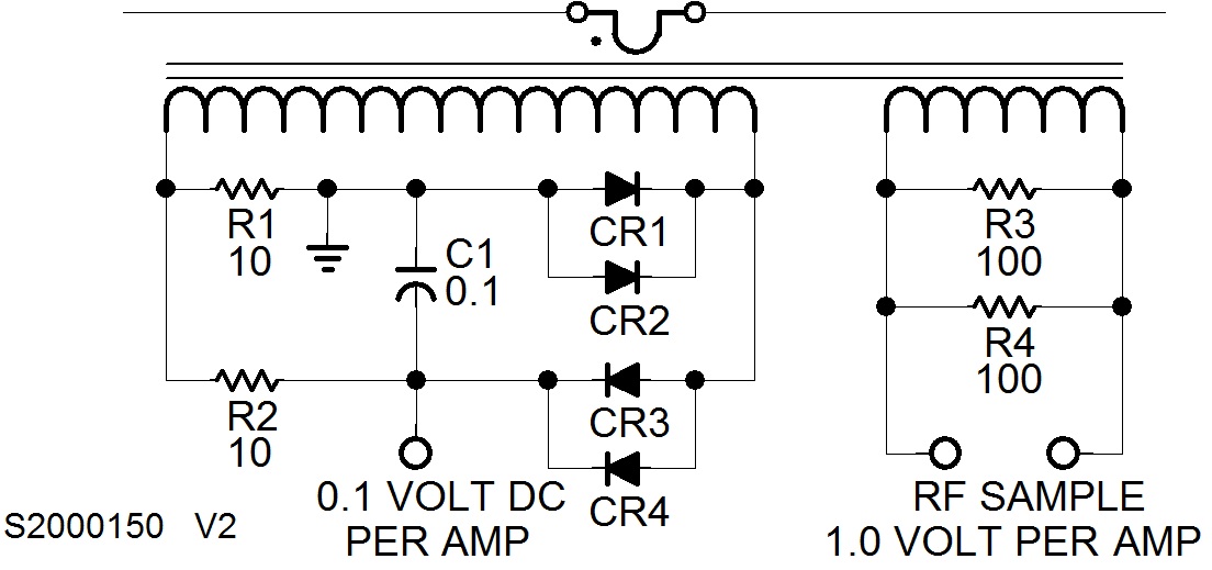
RF Output Sample
The probe has two secondary windings. One 50 turn winding feeding a fifty ohm load provides an RF current sample of one volt per amp that is similar to that of the expensive commercial models that are described above. Limited by the power rating of the resistor the RF probe may be used with currents up to 10 amperes. The output may be connected to instruments other instruments such as an oscilloscope or RF spectrum analyser.
DC Output Sample
The second winding of 141 turns feeds a simple detector circuit that produces a dc output voltage proportional to the RF current of the sampled conductor with a scale factor of 0.1 dc volts per amp (rms). This dc voltage can be measured using a standard battery powered multi-meter that is largely unaffected by the antenna’s electro-magnetic field. Provided that the output of the fifty turn winding is shorted, this DC output may be used to sample RF currents up to 30 amperes.
Parts List
- Philips Ferrite U Cores Type U64 3C80 (2)
- 24 AWG magnet wire (70 ft)
- Diode Type IN4938 (4)
- Resistor, Metal Film 10 ohm, 1/4 W (2)
- Resistor, Metal Film 100 ohm, 2 W (2)
- Capacitor, Ceramic, 0.1 µF, 100 V (1)
- Plastic tube 13/16 i/d x 1 ¾ Long (2)
Jeff
Jeff Welton, has worked with Nautel for 25+ years. He is currently the Nautel Sales Manager for U.S. Central Region but previously he spent 16.5 years as a Nautel Customer Service Technician.
Submissions for this Tips ‘n Tricks column are encouraged and if published you’ll receive a Nautel T-shirt. Submissions should be typed and emailed, with high resolution photos, to [email protected] using the subject line Tips ‘n Tricks.


