
Checking Ground Radial Integrity without Digging
Last issue I threw out a little challenge – promising swag to the first responder who could tell me how to check ground radial integrity without digging. Within hours several replies came in, but the grand prize winner is Steve Callahan, of WVBF in Middleboro, MA, who gave not one, but two suggestions…
“Version #1: You hold your FI meter upside down with the antenna in the cover low to the ground and in line with the suspected radials. Select the right scale and walk the radials in or out. You can screw in a handle in the bottom where you normally would screw in a tripod to make the job a little easier.
Version #2: You get a hockey stick and make multiple windings of transformer wire around the blade. You run the wire back up to the external antenna input to the FI meter. Select the right scale, keep your hockey stick blade on the suspected radial and walk them in or out. This version saves your back muscles.”
Honorable mention goes to other responses received (listed in the order that they’re time stamped in my email):
 Chuck Lakaytis, Lakaytis Broadcast Service in Villa Ridge, MO and teller of all the good stories about broadcasting above the Arctic Circle, referenced a system very similar to Steve’s version #1 above, as taught to him by the one and only Stephen Lockwood. The primary difference was that this method desensitizes the receiver on the FIM by shorting the antenna input with a screw. Chuck provided a link to Hatfield and Dawson’s website giving pictorial detail – you can find it near the bottom of the downloads list at www.hatdaw.com (I’m on the road and hadn’t thought to ask permission ahead of time, so I won’t publish the entire link, but I will beg forgiveness for stealing the related photo (right) – all credit to the folks at Hatfield and Dawson for the wealth of information they provide).
Ed Dulaney, Townsquare Kansas, reminded me that, “The first way is to wait until copper thieves steal them… well, that’s the way to find out where they WERE and not where they are!” He also uses Steve’s version #2.
Josh Bohn, of Bohn Broadcast Services in Birmingham, AL, also weighed in with the shorted antenna input variation as taught by Mr. Lockwood.
Thanks very much to everybody – Mr. Callahan, if you send us a shipping address, we’ll get some goodies off to you!
 A couple of other items that came up since the last issue of Waves were received as a result of conversations held during our NUG @ NAB sessions on the Sunday prior to the NAB show – I figured these might be worthy of further discussion, so I’m using my pulpit to advance the topics.
First, during the NUG sessions, I had a great discussion with Guy West, of Far East Broadcasting, about PoE and data line surge protection, especially given the rise of WLAN links for STL and telemetry purposes – he’d recommended a line sold by Polyphasor/Transtector a good idea!
How to Make a Quarter Wave Stub
Second, there was a rather lively discussion at the NUG of all the ways a VS Series transmitter could be used to replace an exciter and IPA in older transmitters; updating areas which can be prone to failure. One of the items that came up was to provide a DC path to ground at the VS transmitter output, in case of a failure in the isolation circuitry at the final stage – a shorted blocker could have pretty catastrophic results if several kV were fed into the VS unit’s output connector. What I suggested at the time was installing a quarter wave stub at the VS transmitter output to provide this path. Further emails were exchanged after NAB with David Halperin of Townsquare Media of El Paso, as we explored this topic in more detail. Since a quarter wave stub can be used in several places (it’s great lightning protection at a transmitter output, for example), I thought it might be worth exploring this in more detail.
While the VS Series transmitters have DC continuity to ground at the RF output, as well as a gas discharge tube rated at 350V to add further protection, the stub has merit for situations where the transmitter internal coil would not be sufficient, such as lightning or high voltage DC above 350V present after the transmitter’s output connector. The quarter wave stub should be of substantial diameter to improve the already low DC impedance at the transmitter output and should include a connection to the station reference ground (see diagram below).
The concept is pretty simple – at RF, the impedance seen 90 degrees from a short circuit is very high, however, for DC, it’s still a short. Thus, a length of coax 90 degrees long (relative to the carrier) terminated in a short can be “Tee-d” into a circuit without affecting operation at carrier frequency, but provides a great DC path to ground for transients and static (or high voltage DC coming back from a failure in a later stage).
So, it’s a simple concept, how hard can it be to make? Well, the most important part is calculating the length – for this, the formula λ=C/F (wavelength = speed of light/frequency) is all we need to work with. Because we’re cutting our coax to fractions of an inch, we’ll want speed of light expressed as 1.18028527 × 1010 inches per second and frequency in Hz.
For example, at 96.5 MHz, or 96,500,000 Hz, λ=11,802,852,700/96,500,000 or 122.31 inches. 90 degrees equals ¼ wavelength, so for 96.5 MHz, 1/4λ=30.58”.
Keep in mind that, when calculating the length of your quarter wave stub, you also need to factor in connectors – for example, the “T” that the stub will connect to and whatever connector is on your stub assembly to mate with the “T” – effectively, your measurement of quarter wavelength needs to go from the junction with the center conductor of the T to the point at which the center conductor is shorted to the shield.
One other very important item (here’s the answer to your second email, David!) is the velocity factor of the coax you’re using – it needs to be factored into your equation as a direct multiplier. Therefore, in the example above, if we are using RG213, which has a velocity factor of 0.66, our quarter wave stub will need to be 30.58” x 0.66, or 20.18” long. Velocity factor can be found, expressed in either decimal format or as a percentage, on the specification sheet for whatever cable you plan on using.
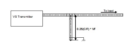
To sum it up, you select a cable appropriate to the power and frequency, calculate a quarter wavelength (taking velocity factor into effect), subtract the length of the T and mating connector and cut your coax accordingly, shorting the far end from the T with a good mechanical and electrical (solder) bond.
Another question that David raised was how you test your quarter wave stub, before installing it – obviously a sweep with a network analyzer would do the trick, but that might be a piece of equipment a lot of folks just don’t have. An easier solution would be to use the VS Series transmitter as your test bed – remember you can turn a VS300 down to 8 Watts. Just connect one end of the T to the transmitter output, the other end to a 50 ohm load, set the transmitter to its minimum power and turn it on. If you did it right, VSWR should be the same with the stub connected as it is when the transmitter is connected directly to the load with no stub installed. You could go a step further and set the transmitter to various frequencies above and below the usual carrier and confirm that VSWR does increase as you move away from the carrier frequency for which the stub was designed. Definitely, you want to be sure that VSWR is acceptable for the entire occupied bandwidth of your signal.
That’s about it until the next issue, keep the thoughts, ideas and comments coming!
Jeff
Jeff Welton, has worked with Nautel for 25+ years. He is currently the Nautel Sales Manager for U.S. Central Region but previously he spent 16.5 years as a Nautel Customer Service Technician.
Submissions for this Tips ‘n Tricks column are encouraged and if published you’ll receive a Nautel T-shirt. Submissions should be typed and emailed, with high resolution photos, to [email protected] using the subject line Tips ‘n Tricks.
